
 Алгебра
 Английский
 Биология
 География
 Геометрия
 История
 Русский
 Обществознание
 Физика
 Химия
Химия Информатика
 Литература
 Математика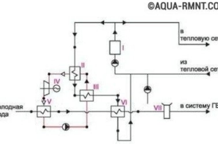
Ответ:
Analysis of the Technical Diagram:
The image displays a schematic diagram of a system involving heat exchangers and pumps. Several components are labeled with Roman numerals:
- I: Likely a heat exchanger or a control unit.
- II: Labeled as a heat exchanger with wavy lines indicating heat transfer.
- III: Another heat exchanger, similar in design to II.
- IV: Appears to be a turbine or a similar rotating machine, connected to a generator symbol.
- V: A heat exchanger.
- VI: A heat exchanger.
- VII: A component, possibly a filter or a control valve.
Textual elements in the diagram include:
- 'Холодная вода' (Cold water): Indicates the input of cold water into the system, likely at component V.
- 'в тепловую сеть' (to the heating network): Suggests an output to a heating system.
- 'из тепловой сети' (from the heating network): Suggests an input from a heating system.
- 'в систему ГВС' (to the domestic hot water system): Indicates an output to a domestic hot water system.
The diagram illustrates a complex process involving fluid circulation and heat exchange, potentially part of a building's heating, ventilation, and air conditioning (HVAC) system or a power generation cycle.
