
 Алгебра
 Английский
 Биология
 География
 Геометрия
 История
 Русский
 Обществознание
 Физика
 Химия
Химия Информатика
 Литература
 Математика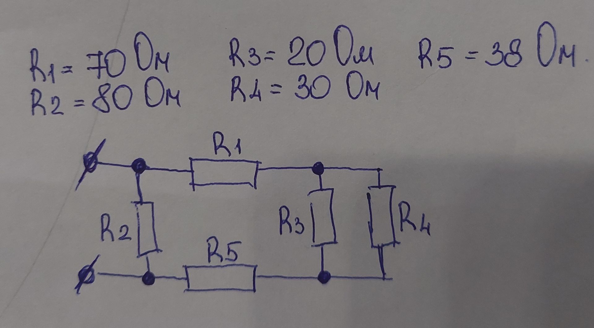
Ответ:
Circuit Analysis:
The image displays an electrical circuit diagram along with the values of its components.
Component Values:
- \( R_1 = 70 \text{ Ом} \)
- \( R_2 = 80 \text{ Ом} \)
- \( R_3 = 20 \text{ Ом} \)
- \( R_4 = 30 \text{ Ом} \)
- \( R_5 = 38 \text{ Ом} \)
Circuit Topology:
The circuit consists of five resistors labeled \( R_1 \) through \( R_5 \).
\( R_1 \) appears to be in series with a parallel combination of \( R_2 \) and \( R_5 \). This entire section is then in parallel with another branch containing \( R_3 \) and \( R_4 \) in series.
Specifically:
- \( R_1 \) is connected in series with a node.
- From this node, there is a branch containing \( R_2 \) and \( R_5 \) in series, connecting to another node.
- Also from the first node, \( R_3 \) is connected in parallel to \( R_2 \) and \( R_5 \).
- \( R_3 \) is in series with \( R_4 \) in a separate branch, connecting to the same second node.
- \( R_4 \) is in series with \( R_3 \).
- The second node is connected to the other terminal of the circuit.
The diagram also shows input terminals, likely for a voltage source or connection points.
