
 Алгебра
 Английский
 Биология
 География
 Геометрия
 История
 Русский
 Обществознание
 Физика
 Химия
Химия Информатика
 Литература
 Математика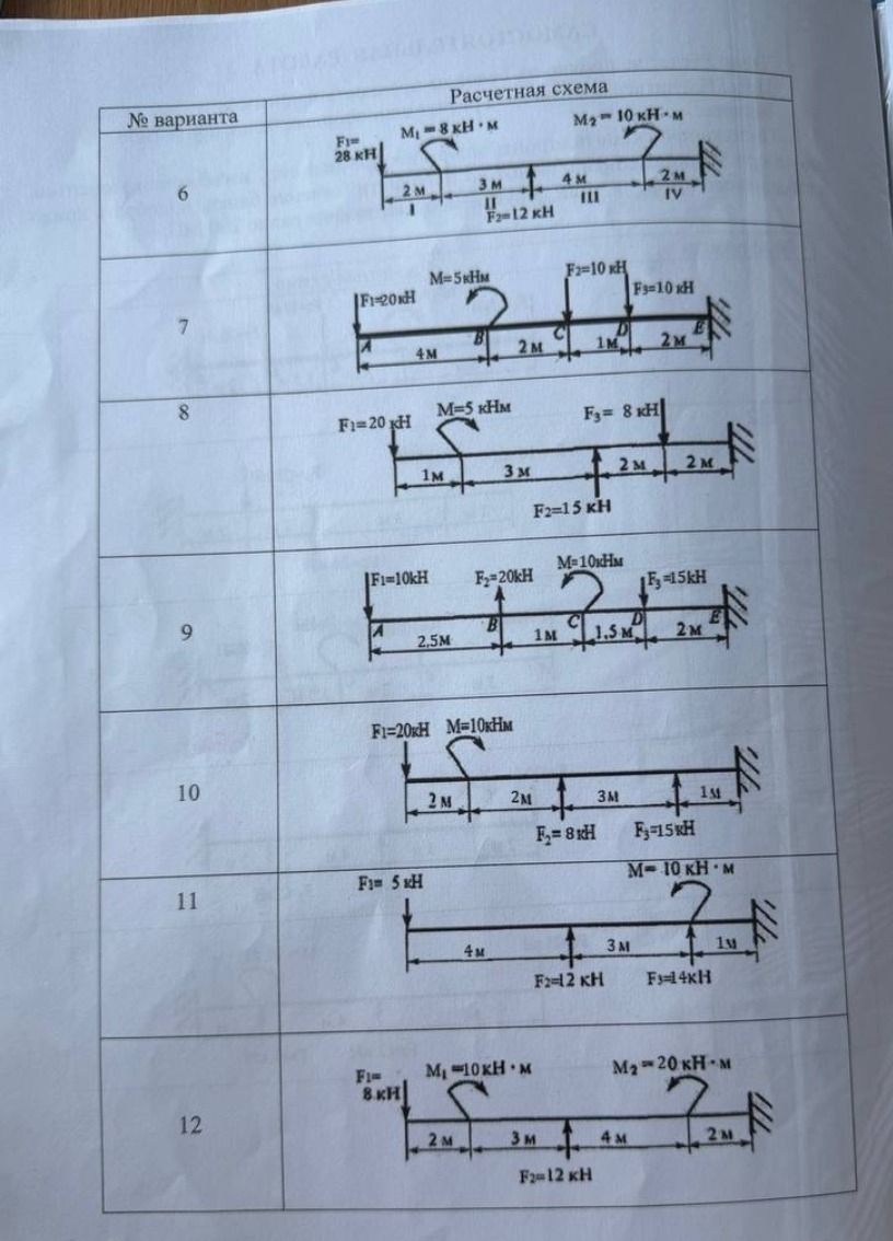
Ответ:
Analysis of Calculation Schemes
The image displays various calculation schemes for engineering problems, labeled by variant numbers (from 6 to 12). Each scheme represents a beam with applied forces and moments, along with dimensions.
Scheme 6:
- Beam with supports at the ends.
- Applied forces: \( F_1 = 28 \text{ кН} \) (downward), \( F_2 = 12 \text{ кН} \) (downward).
- Applied moments: \( M_1 = 8 \text{ кНм} \) (clockwise), \( M_2 = 10 \text{ кНм} \) (counter-clockwise).
- Dimensions: Segments of 2m, 3m, 4m, and 2m are indicated. Support types are labeled I, II, III, and IV, suggesting different support conditions.
Scheme 7:
- Beam with supports at the ends.
- Applied forces: \( F_1 = 20 \text{ кН} \) (downward), \( F_2 = 10 \text{ кН} \) (downward), \( F_3 = 10 \text{ кН} \) (downward).
- Applied moment: \( M = 5 \text{ кНм} \) (counter-clockwise).
- Dimensions: Segments of 4m, 2m, 1m, and 2m are indicated. Points are labeled A, B, C, D, E. Supports are at A and E.
Scheme 8:
- Beam with supports at the ends.
- Applied forces: \( F_1 = 20 \text{ кН} \) (downward), \( F_2 = 15 \text{ кН} \) (downward), \( F_3 = 8 \text{ кН} \) (downward).
- Applied moment: \( M = 5 \text{ кНм} \) (counter-clockwise).
- Dimensions: Segments of 1m, 3m, 2m, and 2m are indicated. Supports are at the left end and the right end.
Scheme 9:
- Beam with supports at the ends.
- Applied forces: \( F_1 = 10 \text{ кН} \) (downward), \( F_2 = 20 \text{ кН} \) (downward), \( F_3 = 15 \text{ кН} \) (downward).
- Applied moment: \( M = 10 \text{ кНм} \) (counter-clockwise).
- Dimensions: Segments of 2.5m, 1m, 1.5m, and 2m are indicated. Points are labeled A, B, C, D, E. Supports are at A and E.
Scheme 10:
- Beam with supports at the ends.
- Applied forces: \( F_1 = 20 \text{ кН} \) (downward), \( F_2 = 8 \text{ кН} \) (downward), \( F_3 = 15 \text{ кН} \) (downward).
- Applied moment: \( M = 10 \text{ кНм} \) (counter-clockwise).
- Dimensions: Segments of 2m, 2m, 3m, and 1m are indicated. Supports are at the left end and the right end.
Scheme 11:
- Beam with supports at the ends.
- Applied force: \( F_1 = 5 \text{ кН} \) (downward).
- Applied forces: \( F_2 = 12 \text{ кН} \) (downward), \( F_3 = 14 \text{ кН} \) (downward).
- Applied moment: \( M = 10 \text{ кНм} \) (counter-clockwise).
- Dimensions: Segments of 4m, 3m, and 1m are indicated. Supports are at the left end and the right end.
Scheme 12:
- Beam with supports at the ends.
- Applied force: \( F_1 = 8 \text{ кН} \) (downward).
- Applied forces: \( F_2 = 12 \text{ кН} \) (downward).
- Applied moments: \( M_1 = 10 \text{ кНм} \) (counter-clockwise), \( M_2 = 20 \text{ кНм} \) (counter-clockwise).
- Dimensions: Segments of 2m, 3m, 4m, and 2m are indicated. Supports are at the left end and the right end.
Analysis Complete.
